Hi Chas,
many thanks for your very kind offer, nice to know when you're trusted.

My problem is not with the harness but with the loose and other maybe non C5 connections to the CB.
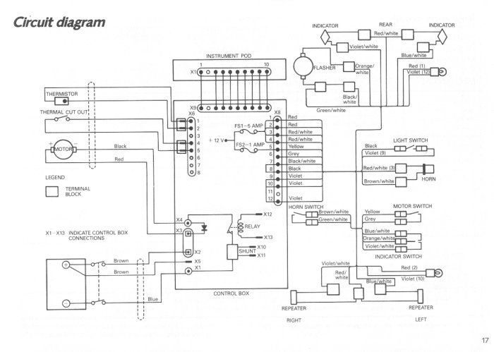
I can't understand the C5 CB cct diagram (C5Alive and Page17.jpg).
All pins are part of X8.
Pin 1 Rear Light Feed +12V.
Pin 2 Front Light Feed +12V.
Pins 10 and 12 are the returns for the above.
This means that Pins 10 and 12 are grounded (0V). If this is the case
HOW can pin 9 (also connected to pins 10 and 12 @ 0V) be the Light Switch Feed when the Light Switch Return, pin 8, is also at 0V?

I can only get at my C5 now and again, so checking is one hell of a problem.
Regards.
KarlG.
P.S. Added Page17.jpg for info. Please don't ask where it came from, I downloaded it years ago and today I can't find it in the IN anymore.
 Author
Topic: Problems with the C5 Cct Diagram. (Read 6778 times)
Author
Topic: Problems with the C5 Cct Diagram. (Read 6778 times)
 info@C5Alive.co.uk